Updated December 12, 2025, by Lucy
I see many engineers struggle with round and cylindrical parts because they do not know how turning fits into modern CNC manufacturing. I want to solve that confusion with a simple explanation.
Turning is a machining process that removes material from a rotating workpiece to produce round, concentric, and precise components. It is reliable, repeatable, and cost-effective for custom parts in metal and plastic.
I want you to keep reading because turning is the foundation of many critical industrial components, yet many buyers do not fully understand how it works or how to choose the right supplier for it.
Fundamentals of Turning?
I know many companies feel lost when they compare different machining methods for their cylindrical parts, and this creates delays and wrong quotes.
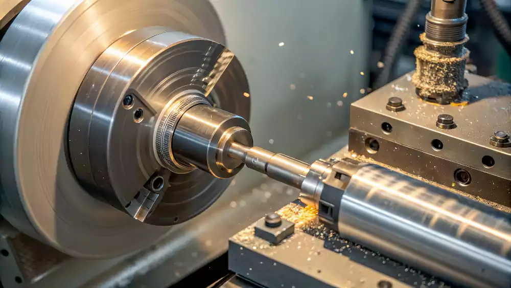
Turning creates shapes by rotating the workpiece around its axis while a fixed cutting tool removes material. CNC controls bring accuracy, consistency, and stable quality for custom components.
What Does Turning Mean in Machining?
I use turning when the part needs a round or concentric shape. The workpiece spins, and the cutter removes material in a controlled way. This makes turning ideal for shafts, pins, valves, rings, sleeves, and similar components. Turning is stable, predictable, and fast. It supports simple and complex shapes as long as they stay symmetrical around the axis.
What Is CNC Turning?
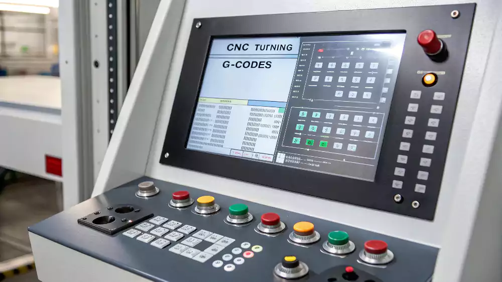
I choose CNC turning for most custom jobs because the machine follows programmed tool paths1. The spindle speed, feed rate, and cutting passes follow instructions, so every part looks the same. CNC turning can also drill, tap, groove, and thread in the same setup. The accuracy is high. Many shops can hold ±0.01–0.02 mm, and some reach tighter tolerances when the material is stable.
Turning vs. Cutting
Cutting is a general term. Turning is one of the cutting methods. Turning is different because the workpiece rotates. This affects which shapes are possible. It also affects roughness, cycle time, and final cost. When I talk to buyers, I always clarify this difference. It avoids wrong assumptions in quotations and prevents design mistakes later.
Turning in the Context of CNC Manufacturing?
Many buyers mix turning and milling. This causes confusion when they send drawings to suppliers and expect fast answers.
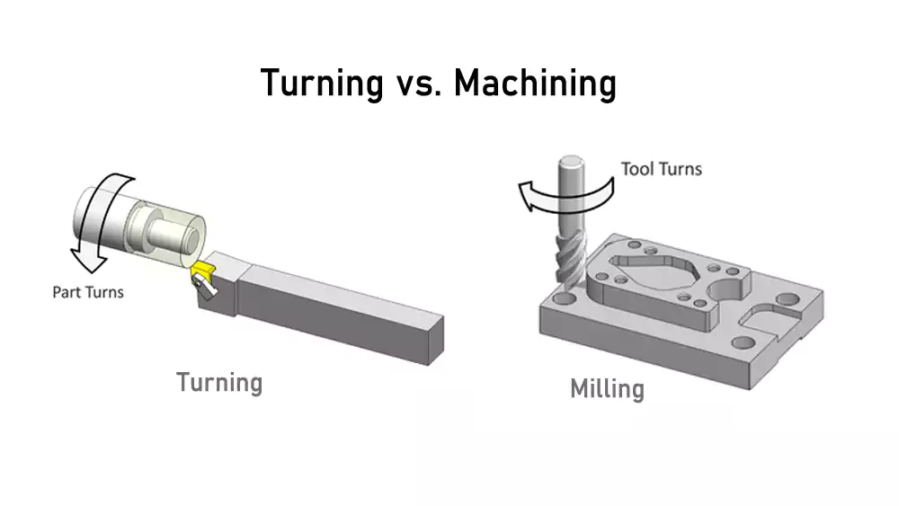
Turning is the preferred method for cylindrical parts, while milling is used for prismatic parts. Hybrid equipment solves more complex shapes by combining both in one machine.
Turning vs. Milling: How to Select the Right Process
I rely on turning when the part has a central axis. Milling is better for flat surfaces or pockets. Turning provides better roundness and better surface finish on circular features. Milling offers better flexibility for complex shapes. I often check if the part could rotate. If yes, turning reduces cost.
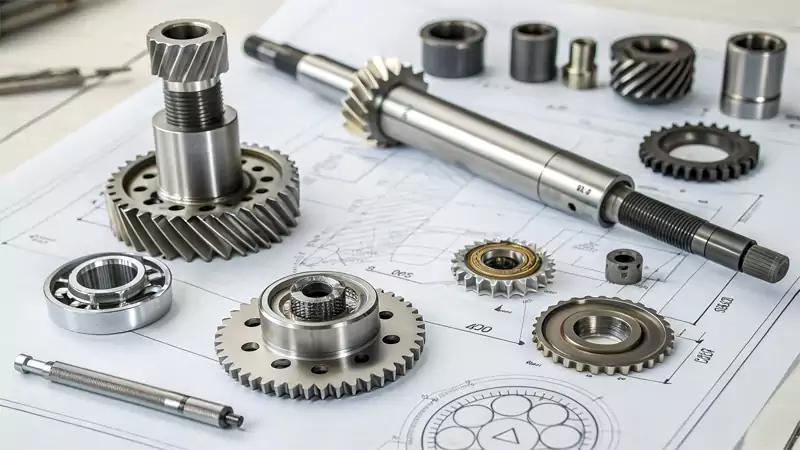
Typical Applications: Parts Best Suited for Turning
Turning is perfect for:
- Shafts and axles
- Bushings and bearings
- Threaded connectors
- Rings and sleeves
- Pins, rollers, spacers
- Valve components
These parts become more efficient and stable when produced on a lathe.
Turning vs. Turn-Milling
I use turn-milling2 when a part needs both round features and milled flats or off-axis holes. This reduces setups and improves accuracy because the entire part stays in the same machine.
Materials, Tolerances, and Surface Finishes?
Many engineers worry about whether the chosen material or tolerance can be achieved in turning, and this often delays sourcing decisions.
Most machinable metals and plastics work well in turning, and CNC lathes produce tight tolerances and smooth surfaces compared to milling.
Common Materials and Machinability
I often machine the following materials on lathes:
| Material | Machinability | Notes |
|---|---|---|
| Aluminum | Excellent | Fast cutting, good for prototypes |
| Brass | Excellent | Clean finish, stable dimensions |
| Steel 45 / 1045 | Good | Wide use for shafts |
| Stainless 304/316 | Medium | Needs slower cutting speed |
| Copper | Difficult | Soft, tends to stick to tool |
| Titanium | Difficult | Needs rigid setup, slow feed |
| POM / Nylon | Excellent | Great for bushings and sliding parts |
Tolerances and Roughness
Typical turning tolerance: ±0.01–0.02 mm
High-precision jobs: ±0.005 mm
Common surface finish: Ra 0.8–1.6 μm
High finish: Ra 0.4 μm or smoother
Capabilities and Limitations in Custom Production?
Buyers often assume a lathe can make any shape. This leads to wrong expectations and poor communication with suppliers.
Turning is strong at round features and long components, but it cannot create complex 3D shapes or deep non-axis pockets without milling.
CNC Turning Capabilities for Custom Parts
I use CNC turning for:
- Diameters from 2 mm to 300 mm
- Lengths up to 800 mm
- Threads (metric, UNC, UNF, G, NPT)
- Grooves, chamfers, radii
- Knurling
- Tight concentricity
This fits most EU automation, robotics, and machinery components.
Limitations
Turning cannot handle:
- Off-axis slots or pockets
- Large flat surfaces
- Complex freeform geometry
- Very thin walls in unsupported areas
These normally require milling or hybrid processes.
Design Tips for Lower Cost
I always tell customers:
- Use standard radii
- Avoid deep narrow grooves
- Keep wall thickness above 1 mm for metals
- Keep thread lengths practical
- Use tolerances only where needed
These points reduce cost and improve delivery time.
Case Study: High-Precision Stainless Shaft
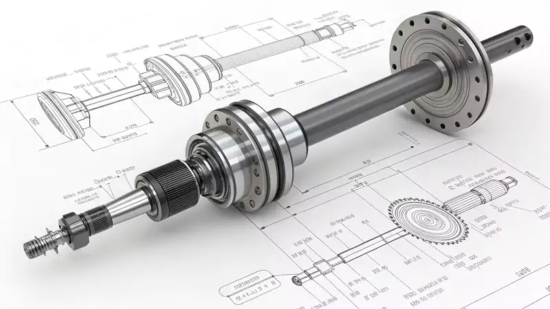
I want to show you one real case from my shop. A customer needed a custom shaft for a robotic joint.
| Parameter | Value |
|---|---|
| Material | SUS3043 |
| Length | 162 mm |
| Diameter | Ø18 mm |
| Tolerance4 | ±0.01 mm |
| Concentricity | 0.015 mm |
| Surface Finish | Ra 0.8 µm |
| Operation | Turning + end-face tapping M6 |
| Batch | 120 pcs |
I solved the stability issue by reducing tool overhang and using a support tailstock. The final batch reached full pass rate. The customer used these shafts in automation equipment for a major EU factory.
Quality Assurance and Supplier Selection?
Many buyers struggle to check quality before mass production, especially when suppliers are outside their region.
Reliable suppliers provide measurement reports, traceability, and stable process control, which helps buyers avoid delays and rework.
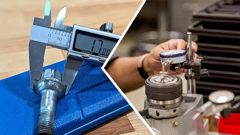
Inspection and Quality Control5
I use these tools daily:
- CMM
- Dial indicators
- Surface roughness testers
- Thread gauges
- Micrometers (0.001 mm resolution)
A stable QC process includes:
- Incoming material check
- First article inspection
- In-process measurements
- Final dimensional report
How to Source a Reliable Supplier
I suggest that buyers check:
- Experience with non-standard parts
- Clear communication and fast quotation
- Realistic tolerances in proposal
- Good surface finish samples
- Batch stability records
- NDAs for design protection
- Flexible prototype-to-production support
A supplier with real machining experience will answer questions clearly and help prevent design mistakes early.
Conclusion
Turning is a stable, accurate, and cost-effective process that helps engineers build reliable round parts for many applications.

-
Exploring CNC tool paths and different types of turning tool paths. ↩
-
This resource will clarify the concept of turn-milling and its benefits, helping you grasp its importance in precision machining. ↩
-
Explore this link to understand why SUS304 is a popular choice for high-precision applications, including its durability and corrosion resistance. ↩
-
Learn about the critical role of tolerance in manufacturing processes, ensuring parts fit and function correctly in high-precision applications. ↩
-
Exploring this resource will provide insights into effective QC practices that enhance product reliability. ↩