Getting press fit tolerances wrong can ruin assemblies. I've seen projects fail when interference fits weren't calculated properly. Precise tolerances prevent parts from slipping or cracking under stress.
Press fit tolerances define the precise amount of interference between a shaft and a slightly smaller hole, creating a strong mechanical joint through friction. These tolerances are critical in precision machining.

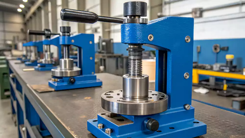
In CNC machining, I’ve seen how critical it is to get press fits right. A good fit saves time, reduces rework, and keeps parts functioning under stress and wear. If you ignore how materials respond to load and heat, you risk costly failures. Let’s break it down.
What Is a Press Fit?
A press fit seems simple: force one part into another, and they stay put. But the reality is more complex—especially in high-precision parts where even 0.01 mm can be the difference between perfect and scrap.
A press fit, also known as an interference fit, is a type of mechanical joint. It is formed when a shaft is forced into a hole that is slightly smaller than the shaft's diameter.
How press fits work?
A press fit is a fundamental engineering concept used to fasten two parts together without any adhesives or traditional fasteners like screws or bolts. The entire connection relies on friction and the compressive forces generated between the two mating parts.
Here’s the core principle:
- Interference1: The external part (like a shaft or pin) is manufactured to be fractionally larger than the internal part (the hole). This dimensional difference is called interference.
- Assembly: The two parts are then forced together, usually with an arbor press or by using thermal expansion/contraction (heating the outer part or cooling the inner part).
- Elastic Deformation: As the shaft is pressed into the hole, both parts elastically deform. The hole stretches slightly, and the shaft compresses slightly.
- Clamping Force: This deformation creates a very high, uniform contact pressure between the two surfaces. This pressure results in a strong frictional force that holds the two parts together, allowing them to resist axial forces and transmit torque.
The amount of interference is carefully calculated based on the materials' elasticity, the desired holding force, and the operating conditions. This calculation determines the specific press fit tolerances that we, as machinists, must achieve. It's a simple concept in theory, but requires extreme precision in CNC machining to execute correctly.
How Many Categories of Press Fits Are There?
Is every press fit the same? Are there different levels of tightness or interference for different applications, and how are they categorized?
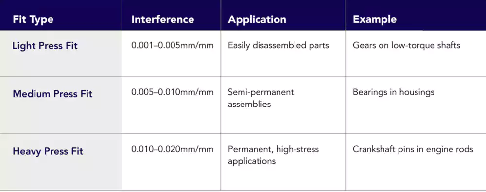
Press fits are categorized based on the amount of interference. The main categories are drive fits (light force), force fits (heavy force), and shrink fits (requiring temperature change for assembly).
Diving Deeper into Press Fit Categories
Not all interference fits are created equal. The amount of interference—the key difference between the shaft and hole diameters—is carefully chosen based on the application's needs. For an engineer like David, selecting the right category is essential for ensuring the joint is strong enough but doesn't over-stress the components. Standards like ANSI B4.12 classify these fits.
Here are the main categories, ranging from lightest to heaviest interference:
| Fit Category | Level of Interference | Assembly Method | Typical Applications |
|---|---|---|---|
| Drive Fits3 (FN 1 & FN 2) |
Light Interference. The interference is minimal, creating a semi-permanent joint. | Can be assembled with light pressure, often using a mallet or arbor press without excessive force. | For parts that must be held securely but may need to be disassembled for repair without damaging the components. Used for locating pins and some gears. |
| Force Fits (FN 3 & FN 4) |
Medium to Heavy Interference. The interference is significant, creating a strong, permanent connection. | Requires high pressure from a hydraulic press for assembly at room temperature. | For parts that must transmit high torque or withstand significant axial forces. Used for mounting bearings, motor rotors on shafts, and other permanent assemblies. |
| Shrink Fits4 (FN 5) |
Very Heavy Interference. The interference is so great that assembly at room temperature is impractical or would damage the parts. | Requires a significant temperature difference. The outer part (housing) is heated to expand, and/or the inner part (shaft) is cooled (e.g., with liquid nitrogen) to shrink. The parts are then assembled and allowed to return to the same temperature, creating immense pressure. | For the most demanding applications requiring the highest possible holding force and torque transmission, such as fitting steel rims onto train wheels. |
The specific press fit tolerances for the hole and shaft are defined in engineering standards for each of these fit categories to ensure a predictable and reliable outcome.
What Are the Key Factors That Affect Press Fit Tolerances?
What variables can change the outcome of a press fit? Why can two parts with the same dimensions sometimes fit perfectly and other times fail?
Key factors affecting press fit tolerances include material properties (elasticity, thermal expansion), surface finish, operating temperature, and the physical dimensions and rigidity of the mating parts.
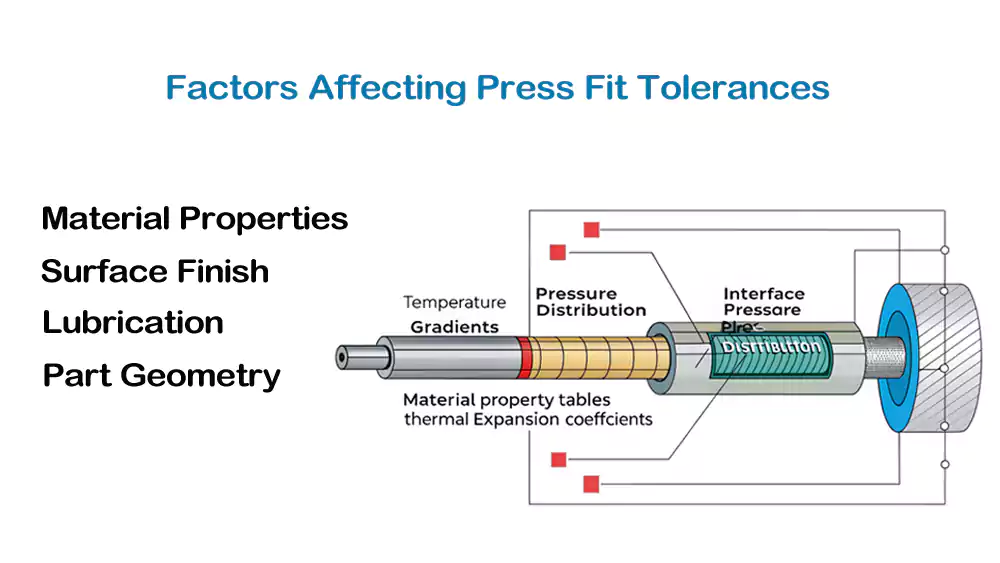
Diving Deeper into Influencing Factors
As I've learned from my years in precision machining, achieving a successful press fit is about more than just hitting the numbers on a drawing. It’s about understanding the physics of the assembly. An engineer like David needs to consider these factors during the design phase to ensure the calculated tolerances will work in the real world.
Here are the key factors that influence the effectiveness of a press fit:
-
Material Properties:
- Modulus of Elasticity: This measures a material's stiffness. A stiffer material will deform less, creating higher stresses for the same amount of interference. The calculation must account for the elasticity of both the shaft and the housing materials.
- Coefficient of Thermal Expansion: This is critical. If the assembly will operate at a high temperature, both parts will expand. If they are made of different materials (e.g., a steel shaft in an aluminum housing), they will expand at different rates. Aluminum expands more than steel, so the fit will become looser at high temperatures. This must be factored into the initial interference calculation.
-
- A rough surface finish has microscopic peaks and valleys. During a press fit, these peaks can be flattened or worn down, which effectively reduces the amount of interference and lowers the holding force. For critical press fits, a very smooth surface finish (achieved through grinding or honing) is required.

-
Lubrication:
- Using a lubricant during assembly can help prevent galling and scoring of the surfaces, but it also slightly reduces the frictional holding force. This trade-off needs to be considered.
-
Part Geometry:
- The wall thickness of the housing and whether the shaft is solid or hollow affects how much they deform under pressure. A thin-walled housing will stretch more easily than a thick, rigid one, which changes the final contact pressure.
A successful design accounts for all these variables, ensuring the press fit tolerances specified on the drawing will result in a reliable joint under its intended operating conditions.
What are the different types of tolerance standards?
How do engineers and machinists communicate about tolerances universally? What are the standard systems used to define fits like press fits?
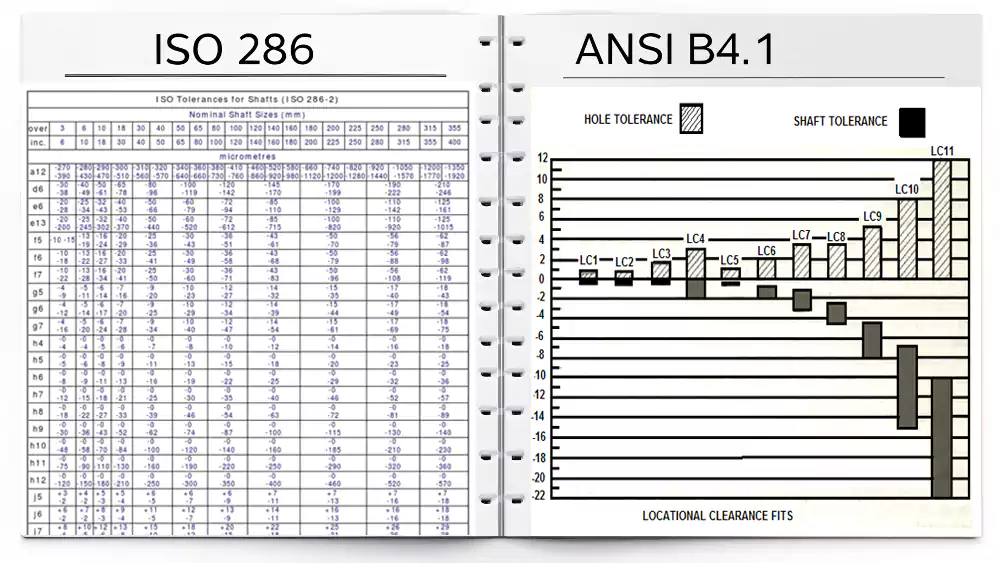
The two primary international standards for fits and tolerances are the ISO System of Limits and Fits (ISO 286) and the ANSI Standard (ANSI B4.1) used in the United States.
Diving Deeper into Tolerance Systems
To ensure that a shaft made in one country will fit perfectly into a housing made in another, engineers rely on internationally recognized standards for specifying limits and fits. For a Lead Engineer like David, using these standards on his drawings is essential for clear and unambiguous communication with any manufacturing partner worldwide.
The two main systems are:
1. The ISO System of Limits and Fits (ISO 286)5
This is the most widely used system globally. It is incredibly comprehensive and systematic.
- Fundamental Deviation: It uses letters to define the position of the tolerance zone relative to the basic size. Uppercase letters (e.g., H, J, K) are for holes, and lowercase letters (e.g., h, p, s) are for shafts. An "H" hole is a standard base hole, while "p" and higher letters for shafts create interference fits.
- Tolerance Grade (IT Grade): It uses numbers (e.g., IT6, IT7, IT8) to define the size of the tolerance zone (the "quality" of the dimension). A smaller number means a tighter tolerance.
- Example of a Press Fit: A common press fit might be specified as 50 H7/p6. This tells a machinist that for a 50mm nominal size, the hole should be machined to the "H7" tolerance and the shaft to the "p6" tolerance. This combination guarantees a specific amount of interference.
2. The ANSI Standard (ANSI B4.1)6
This is the standard predominantly used in the United States. It is conceptually similar to ISO but uses a different naming system.
- Fit Classes: It defines different classes of fits using letters. For interference fits, the classes are:
- LN: Locational Interference Fits (for alignment)
- LT: Transition Fits (can be a small interference or clearance)
- FN: Force or Shrink Fits (for true press fits)
- Example: A heavy press fit might be specified as FN 4. The standard tables then provide the specific upper and lower limits for both the hole and the shaft for a given nominal size.
While the nomenclatures are different, both systems provide a robust framework for defining press fit tolerances so that parts can be manufactured and assembled with predictable and reliable results.
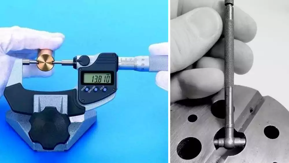
How to measure and calculate press fit tolerances?
You can’t improve what you can’t measure. And in CNC machining, every micron matters. How do you determine the right numbers for a press fit? And how do machinists verify that they have achieved those numbers with precision?
Press fit tolerances are calculated based on material properties and desired holding force. They are measured using high-precision tools like micrometers, bore gauges, and CMMs to verify the final dimensions.
Diving Deeper into Calculation and Measurement
Achieving a successful press fit involves both careful calculation during the design phase and precise measurement during manufacturing.
Calculation
The calculation of press fit tolerances is a detailed engineering task. David would need to consider several factors to determine the required amount of interference.
- Define Required Pressure: First, he determines the contact pressure needed between the shaft and hole to transmit the required torque or hold against the expected axial force.
- Use Lame's Equation: This engineering formula relates the contact pressure to the interference, material properties (like Modulus of Elasticity and Poisson's Ratio), and the diameters of the parts.
- Solve for Interference: By working through the formula, he can calculate the ideal amount of interference needed to generate that pressure.
- Assign Tolerances: He then assigns tolerances to both the hole and the shaft based on a standard system (like ISO 286) to ensure that even at the worst-case tolerance stack-up (largest hole, smallest shaft), the minimum required interference is still achieved.
Measurement
As a machinist, my job is to ensure the physical part matches those calculated numbers. We cannot rely on guesswork; we must use precision metrology tools.
- Shaft Measurement: The outside diameter of the shaft is measured using a micrometer. A standard micrometer is accurate to 0.0001 inches (about 2.5 microns).
- Hole Measurement: Measuring the inside diameter of the hole accurately is more challenging. We use:
- Bore Gauges: These tools have sensitive contacts that transfer the hole's diameter to an external measuring instrument.
- Pin Gauges: A set of precision-ground pins of known, incremental diameters. We find the largest pin that fits in the hole and the smallest that doesn't to determine its size.
- Coordinate Measuring Machine (CMM): For the highest accuracy, a CMM uses a touch probe to measure multiple points around the inside of the hole and calculate its precise diameter and roundness.
This combination of engineering calculation and precision CNC machining and measurement is what makes reliable press fits possible.
Press fit tolerance tables
Standardized tolerance tables simplify press fit selection for common applications. These tables provide tested interference ranges that ensure reliable performance across different diameter ranges and materials.
Press fit tolerance tables specify interference ranges, tolerance classes, and recommended applications for standard shaft and hole combinations. Tables are organized by diameter ranges with separate sections for different fit classes.
Diving Deeper into Reading Tolerance Tables
Engineering standards like ISO 286 provide comprehensive tables that eliminate the need for engineers and machinists to calculate press fit tolerances from scratch for every application. These tables provide the "answer" for standard fits. For an engineer like David, knowing how to read these tables is a fundamental skill.
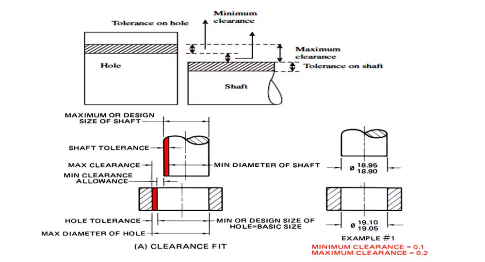
Let's look at a simplified example for a 50mm H7/p6 fit, which is a common force fit.
Nominal Size: 50 mm
| Feature | Fit Designation | Lower Limit (mm) | Upper Limit (mm) | Tolerance Range (mm) |
|---|---|---|---|---|
| Hole | H7 | 50.000 | 50.025 | 0.025 |
| Shaft | p6 | 50.042 | 50.058 | 0.016 |
How to Interpret This Table:
-
Hole (H7):
- The machinist must produce the hole with a diameter that is no smaller than 50.000 mm (the basic size) and no larger than 50.025 mm.
- The total allowed variation (tolerance) for the hole is 0.025 mm.
-
Shaft (p6):
- The machinist must produce the shaft with a diameter no smaller than 50.042 mm and no larger than 50.058 mm.
- The total allowed variation for the shaft is 0.016 mm.
Calculating the Interference:
Using this table, we can calculate the resulting interference:
- Maximum Interference (Tightest Fit): Occurs with the largest shaft and the smallest hole.
- 50.058 mm (max shaft) - 50.000 mm (min hole) = 0.058 mm
- Minimum Interference (Loosest Fit): Occurs with the smallest shaft and the largest hole.
- 50.042 mm (min shaft) - 50.025 mm (max hole) = 0.017 mm
This table guarantees that for any combination of parts made within these press fit tolerances, the interference will always be between 0.017 mm and 0.058 mm, ensuring a predictable and strong force fit. This is the kind of precision we work with in CNC machining every day.
What Are Typical Techniques for Controlling Press Fit Tolerances?
Achieving tolerances measured in microns requires more than just a standard CNC machine. What special techniques and processes do machinists use to control press fit tolerances?
Effective press fit tolerance control combines precision machining techniques(high-precision CNC machining), temperature-controlled environments, proper tooling design, statistical process control, and and often secondary finishing processes like grinding, honing, or lapping to achieve the final size and surface finish.
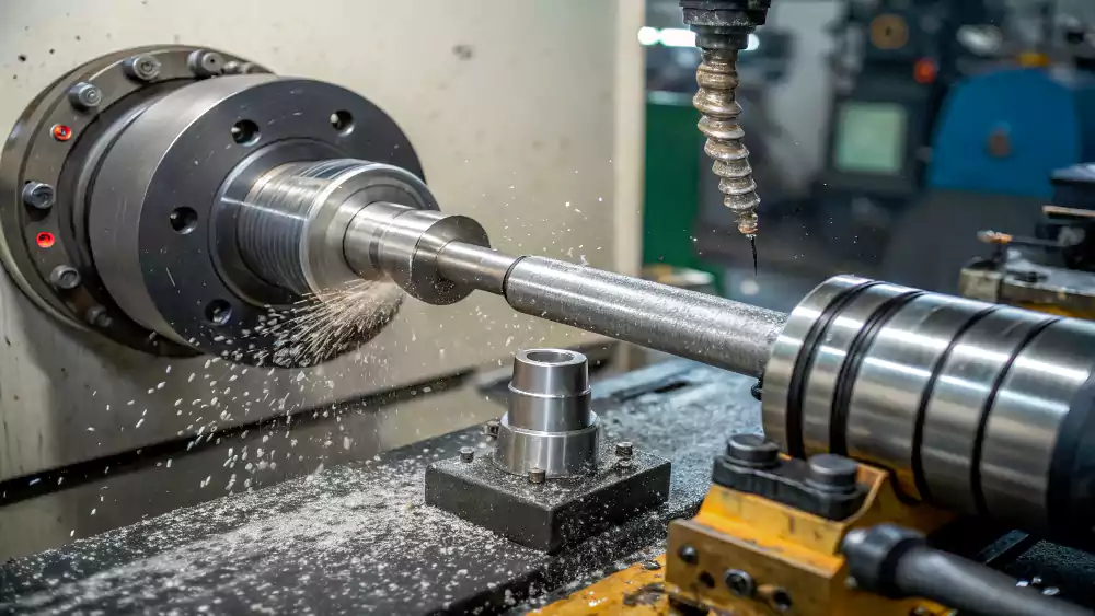
As a machinist, I know that hitting the tight press fit tolerances required for an FN4 fit or an H7/p6 callout is where true precision machining comes into play. It requires a combination of the right equipment, environment, and process control.
Here are the techniques we use at Allied Metal to achieve this level of accuracy:
Process control methods
| Technique | Accuracy Gain | Best For |
|---|---|---|
| Cryogenic shrinking | ±0.0003" | Brittle materials |
| Induction heating | ±0.0005" | Large assemblies |
| Force monitoring | ±2% | Production runs |
| Tapered entries | ±0.001" | Long engagements |
Quality assurance steps
- Statistical process control on diameters
- First/last part validation
- Insertion force trend analysis
- Post-assembly ultrasound inspection
Material-specific approaches prevent failures. For stainless steel, we polish surfaces to 16μin Ra to reduce galling. With plastics, use chilled assembly to prevent rebound. Always design lead-in chamfers (minimum 15°) - I've seen sharp edges scrape off interference material during insertion. For mass production, implement automated vision systems to check part orientation before pressing.
What Are Common Applications of Press Fit Tolerances?
Where are press fits used in the real world? What are some common examples of applications that rely on these precise interference fits for their function?
Common applications for press fits include mounting bearings into housings, fixing gears and pulleys onto shafts, and inserting hardened dowel pins for precise alignment in machine assemblies.
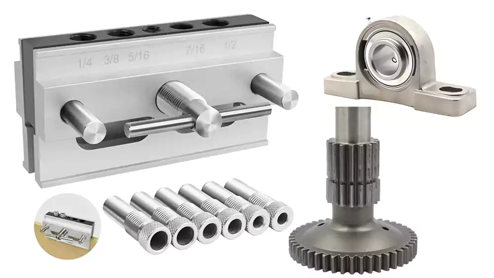
Diving Deeper into Real-World Applications
Press fits are a fundamental building block of mechanical design, found in countless machines and devices. For an engineer like David, these applications are part of his daily work in designing robust industrial automation systems.
Here are some of the most common applications where press fit tolerances are critical:
-
Mounting Bearings:
- This is perhaps the most common use. The outer race of a ball or roller bearing is pressed into a precisely machined hole (the bearing housing or bore). The inner race is often pressed onto a shaft. The interference fit ensures the bearing is held securely and cannot spin in its housing, which would cause rapid wear and failure.
-
Attaching Gears, Pulleys, and Sprockets to Shafts:
- To transmit torque from a shaft to a gear or pulley, a strong connection is needed. A heavy press fit creates a powerful frictional bond that can handle high torque loads without the need for keys or splines, resulting in a simpler and often more balanced assembly.
-
Inserting Dowel Pins:
- Hardened steel dowel pins are used for very precise alignment between two mating parts, like two halves of a fixture or a mold. These pins are pressed into accurately located holes with a light interference fit. This ensures that every time the two parts are assembled, they return to the exact same relative position.
-
Valve Seats and Bushings:
- In engine cylinder heads and valve bodies, hardened valve seats and bronze guide bushings are pressed into the parent casting. The press fit holds them securely in place despite constant temperature changes and mechanical stress.
In all these examples, the reliability of the entire assembly depends on the CNC machining of components to the correct press fit tolerances. It’s a testament to how critical precision is in modern manufacturing.
Conclusion
Press fit tolerances are essential for creating strong, reliable mechanical joints. Success requires a deep understanding of materials, precise calculation, and expert CNC machining and finishing techniques.
-
Understanding interference is crucial for achieving the right fit and ensuring strong connections in mechanical assemblies. ↩
-
Exploring the ANSI B4.1 standard provides insights into the classification and specifications of interference fits, essential for engineering precision. ↩
-
Drive Fits are vital for creating secure yet disassemblable joints; learn more about their applications and benefits. ↩
-
Shrink Fits are used in high-stress applications; understanding them can enhance your knowledge of advanced engineering techniques. ↩
-
Explore this link to understand the comprehensive framework of ISO standards for tolerances and fits, crucial for global engineering. ↩
-
Discover the ANSI B4.1 standard to see how it defines fit classes and their applications in U.S. engineering practices. ↩